Optimization of hollow-fiber dialyzers
Remark: A proper representation of the formulae requires that Windows’ font Times New Roman in a newer version for Windows 2000 and up is installed, which includes Greek letters and some mathematical symbols.
Here is a description of how to optimize the design of a hollow-fiber dialyzer.
The steps are the following – assuming countercurrent operation (which is the only feasible case).
-
Choose the type of fiber you want to use.
-
Decide what total membrane area A you want to have (this can later be adjusted for a desired clearance for, e.g., urea).
-
Calculate the optimum packing density. This is the fiber density in a cross section of the bundle which results in [approximately] the same pressure drop along the bundle on both sides under normal operation conditions: in the blood flow and in the dialysate flow. This “rule of thumb” is empirical and has been experimentally well confirmed. It also results in a reasonably small diffusion boundary layer on the dialysate side.
-
Decide what minimum ultrafiltration rate Qu0 you want to allow for. This is the ultrafiltration rate when the transmembrane pressure is zero at the blood outflow (“venous”) end of the dialyzer. Why? Because there must for security reasons (safe operation) never be a negative transmembrane pressure anywhere, since otherwise microparticles or germs could enter the blood through a pinhole or the like. The limit case is the one mentioned: transmembrane pressure zero at the venous end of the active part of the bundle. This is the case with the lowest safe ultrafiltration rate.
-
Determine the free (active) fiber length. Since according to point 3 the pressure drop Δp is the same on both sides (in the dialysate flow and in the blood flow), the maximum transmembrane pressure in a countercurrent arrangement is 2Δp at the “arterial” end of the bundle and zero at the “venous” end at minimum ultrafiltration rate. The mean transmembrane pressure, therefore, is Δp. The minimum ultrafiltration rate then is Qu0 = kuA·Δp0, where ku is the ultrafiltration coefficient for the fiber wall and Δp0 the allowed pressure drop for safe operating conditions. From the chosen value of Qu0 (point 4), Δp0 can be calculated, and from that the active fiber length that leads to this value of Δp0 for blood (which according to point 3 is the same as in the dialysate).
-
Calculate the resulting clearance for, e.g., urea and – if desired – adjust the membrane area A.
A further step then is to choose a suitable design of the dialyzer headers and the dialysate in- and outlet arrangements. Considerations for optimization of such designs will be given separately.
CALCULATION OF THE OPTIMAL PACKING DENSITY OF THE FIBERS
The pressure drops in the active blood and dialysate pathways
are, resp. [1,2]:
![]()
and
![]()
where
(3) F(t) = 4(t2 - ln t) - 3 - t4,
and
(4) t = re√πn.
Here:
Δpb
= pressure drop in the blood flow path over the active length of the bundle,
Δpd
= pressure drop in the
dialysate flow path over the active length of the bundle,
Qb = blood flow rate,
Qd = dialysate flow rate,
ηb
= viscosity of the blood,
ηd
= viscosity of the dialysate,
L = active fiber length,
N = number of fibers in the bundle,
ri = internal radius of the swollen fiber
(since
it swells in a watery solution),
re = external radius of the swollen fiber,
n = packing density (number
of fibers per mm2
bundle cross section).
From this follows:
At a hematocrit of 40
%, as is commonly assumed in dialyzer design, the relation ηb/ηd
is approximately 3.5 at 37° C [3].
More exact values can be derived from the relations presented
here [4].
The viscosity of water in cp as a function of
temperature T in °C is η ≈ 0.2879 + 1.3846 e-0.03332 T,
valid in a temperature range from 30° to 40° C.
The “standard
operating condition” for a dialyzer used to be (and
probably still is) Qb
= 200 and Qd
= 500 ml/min.
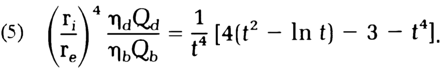
With these values we can calculate the parameter t , e.g., through iteration of the
(5) above, and then n from (4):
(6) n = t2/(πre2).
CALCULATION OF THE OPTIMAL ACTIVE FIBER
LENGTH
The optimization criterion is, as per point 4 above, that a minimum safe
ultrafiltration rate is defined and the length is to be calculated accordingly.
This rate is
(7) Qu0 = kuA·Δp0,
where ku is the ultrafiltration coefficient for the fiber wall and Δp0 the allowed pressure drop for safe operating conditions. The active area of the dialyzer is
(8) A = 2πriLN.
If we set Δpb = Δpd, we get, from (1) and (8)
(9) Qu0 = 16ηbkuQbL2/ri3.
From this the corresponding active fiber length L can be calculated under an appropriate operation condition, such as Qb = 200 ml/min (the standard value 500 ml/min for Qd is included in the above optimization of n).
This optimization step
is the more important the higher the ultrafiltration coefficient
ku
is, but:
Alternatively a suitable active fiber length L can instead
be chosen (from other considerations) and then –
the other way around –
a value of the minimum safe ultrafiltration rate Qu0
prescribed as an operation requirement for the dialyzer. The
ultrafiltration rate must never be lower than that value of Qu0.
It should be born in mind that the value of ku measured on raw fibers in a laboratory may not be the same for fibers which are processed in the sense that they have been washed and dried (cf. here). If there is a difference, the coefficient can be expected to be less in the latter case.
OPTIMIZED DIMENSIONS OF
THE FIBER BUNDLE
The number of fibers in the bundle can now be calculated from (8). The
cross-section area Ab
of the bundle is then
(10) Ab = N/n
and the optimized
bundle diameter (the internal diameter of the dialyzer sleeve) is determined by
![]()
The fiber length to be used for the assembly is the active length L plus additional sections needed in the manufacturing, being the fiber sections in the pottings (before cutting) and – maybe – consideration of the small “varnishing” section (see here). The latter has to be determined experimentally.
CALCULATION OF THE
DIALYZER CLEARANCE
The procedure for calculating the clearance of the dialyzer und various
conditions is described in detail in my articles “Operating Characteristics of
Hollow Fiber dialyzers” [1] and “Calculation
of combined diffusive and convective mass transfer” [2]. The reversed calculation of the dialyzer area A
for a given clearance for, e.g., urea, is difficult. The more suitable procedure
would be to iterate through modifying A until the desired value is
achieved. The discussion of boundary layers in that article may be considered
theoretical and of little importance in practice, since their effects will
unavoidably be more or less included in values resulting from laboratory
measurements on fibers. It is actually very difficult to determine the real
diffusion resistance of the fiber wall itself, without the influence of the
boundary layers in the liquid flows. The calculation is also based on the
assumption that the blood flow inside the fiber would be a Poiseuille flow. Due
to flow characteristics of blood, a pure Poiseuille flow is not possible, but
an exact calculation that considers the real flow state would be exceedingly
difficult. The same, of course, is valid for the calculation above of the
blood-path pressure drop. In practice, however, the calculation as if it would
be a Poiseuille flow is a sufficient approximation.
Furthermore, the calculation of the dialysate-path pressure drop is based on the assumption of a uniformly ordered equidistant and in the cross section hexagonal arrangement of straight fibers. This will, of course, never be the case in reality, since it is impossible to keep up such an arrangement. Again, this is an approximation. Deviations from that ideal arrangement will, however, more or less average out between the thousands of fibers present in the bundle. Effects of turbulence in the dialysate flow – which can to some extent occur locally in the bundle – cannot be considered but are likely to contribute by small amounts to an improvement of the dialyzer performance. Effects of a non-uniform distribution of dialysate flow at the ends of the dialyzer (in the areas of the dialysate ports) can also not be considered in calculations. The design of these areas should be such that non-uniformity of this distribution is minimized.
It should be born in mind that the diffusion permeability of the fiber wall, like the ultrafiltration permeability (see above), may deteriorate by a small amount in the processing of the fibers, mainly through washing and drying (see here).
Mechanical
considerations of dialyzer design as concerns blood port headers are discussed
here.
Mechanical
considerations of dialyzer design as concerns dialysate connection arrangements are discussed
here.
References:
-
Jan Erik Sigdell: “Operating Characteristics of Hollow-Fiber Dialyzers”, Chapter 5 in Clinical Dialysis ed. By Allen R. Nissenson et al., Appleton & Lange, Norwalk, Connecticut, 1990, pp. 97-117
-
Jan Erik Sigdell: “Calculation of combined diffusive and convective mass transfer” in International Journal of Artificial Organs, Wichtig, Milano, Vol. 5, 1982, No. 6, pp. 361-371,
-
William J. Williams et al.: Hematology, McGraw-Hill, New York NY, 1986
-
A. R. Pries, D. Neuhaus and P. Gaehtgens: “Blood viscosity in tube flow: dependence on diameter and hematocrit” in American Journal of Physiology - Heart and Circulatory Physiology, Vol. 263, Issue 6, 1992, pp H1770-H1778