Design of headers
Remark: A proper representation of the
formulae requires that Windows’ font Times New Roman in a newer version for
Windows 2000 and up is installed, which includes Greek letters and some
mathematical symbols. Formulae are partly written in a slightly unconventional
way to enable representation in an html file.
Clotting considerations
Clotting begins when thrombocytes adhere to surfaces. Where the blood flow becomes slow, thrombocytes can more easily adhere. We, therefore, want to avoid stagnation points and regions of slow blood flow. Turbulence due to flow separation from surfaces contributes to thrombocyte adherence and clotting and is also to be avoided.
Headers with a central axial feed of the entering blood
Here one stagnation point is unavoidable: in the center of the cut polyurethane surface, between fiber ends (i.e., where there are no open fiber ends). A more stream-lined design will, however, minimize this effect.
I have extensively studied headers with conventional design (as they were common in the 1980es – I am not aware of newer designs, since I am retired and no more work with these things) using a 33 % glycerin solution at 37° C for simulation of blood viscosity. Flow phenomena can be visualized by means of injection of a dye (e.g., ink) into the inlet tubing. At a “blood” flow of 200 ml/min flow separation was clearly visible in all designs. The dye formed like smoke rings rolling outwards from the center in the blood space under the header at its inner surface. In order to avoid this, there are three possible attempts for a more hemocompatible design:
1. a stream-lined design of the header profile,
2. maintaining a constant radial flow velocity in the space under the header,
3. maintaining a constant tangential flow velocity, and
4. maintaining a constant vectorial sum of the radial and tangential flow velocities.
The space under the header here considered is that for a radius larger than d/2, where d is the inner diameter of the actual blood port (the tube where the blood enters this header space). The radial velocity meant here is the mean value over the header space height at a certain radius and the tangential velocity meant is the mean value over a line perpendicular to the cap profile (hence parallel to that profile).
A calculation according to point 1. above is exceedingly complicated and leads to a differential equation with elliptic integrals (to see what it looks like, click here) even if friction is neglected, and it becomes still more complicated if friction is considered. The calculation according to points 3. and 4. requires the solution of a fourth-degree first-order differential equation. Therefore a calculation according to 2. is chosen, which leads to sufficient results, at least after minor experimental adjustments.
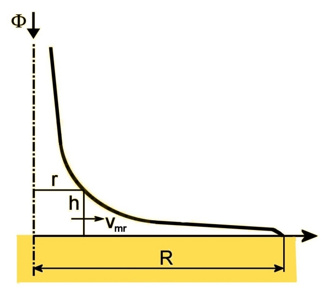
The following figure shows the geometrical basis for calculating a profile with a constant mean radial flow velocity vmr in the header space.
Mass balance for the cylinder of radius r and height h yields
(1) 2πrhvmr = Φ(1 - r2/R2),
where Φ is the entering blood flow and R the outer radius of the inner header space. The left side is the flow through the curved wall of the cylinder and the right side the flow drained into the fiber ends outside that cylinder.
This equation for a constant vmr corresponds to a profile
(2) r = √a²h²+R² - ah,
wherein
(3) a = πvmrR2/Φ.
For this profile r → 0 as h → ∞ since it is calculated for a hypothetical case of vmr being constant for all r, even down to r = 0. Furthermore, laboratory investigations show that there is still a small flow separation from the header wall.
One way to reduce flow separation is to provide kinetic energy for redirection of the flow where the profile in a comparatively sharp way turns outwards from a central and more tubular shape to a flattened shape. The increased kinetic energy builds up more driving pressure at the bend where there is a transit from the higher velocity in the entrance tube to the lower but nearly constant velocity in the radial distribution flow.
This can be done through a soft acceleration of the blood flow before this bend of the flow lines through slightly narrowing a part of the tubular section. A trick for designing this, which has proven to be very successful in practical experiments, is to draw the profile according to the following figure in a skewed coordinate system with a slanted h axis.
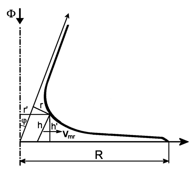
This picture is drawn in an exaggerated manner to show things more clearly.
Recalculating to new rectilinear coordinates h' and r' one gets the equation
(4) r' = √b²h'² + R² - ch',
wherein
(5) b = a/cos φ
and
(6) c = (a - sin φ)/cos φ.
φ is the angle between the h and the h' axes.
This design presumes a frictionless flow. In reality vmr cannot remain high up to r = R with this profile, since the velocity must drop to zero at the inner surface of the header. Here, there is a velocity boundary layer of thickness ε, and when the height h of the cap space reaches this value, the radial flow must drop rapidly with increasing r.
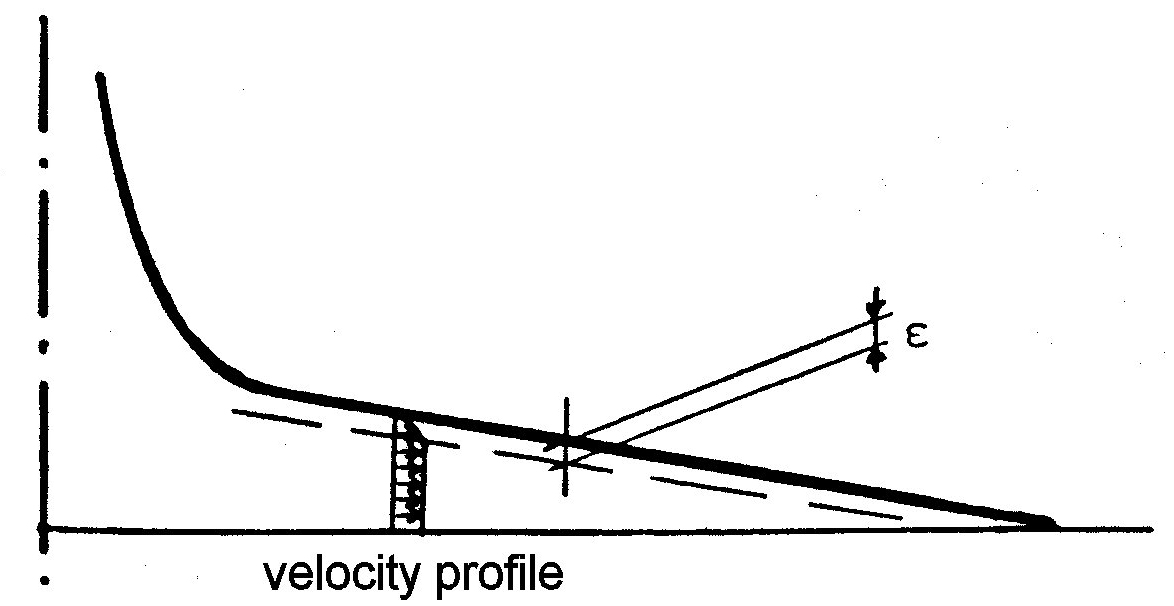
A theoretical consideration of the friction in this boundary layer becomes very complicated. However, the above consideration opens a way for an experimental correction. One only needs to lift the profile by an amount approximately equal to ε, retracting it a little bit from the cut polyurethane surface, so that this boundary layer reaches the resin surface at r = R.. This leads to the equation
(7) r' = √b²(h' - ε)² + R² - c(h' - ε).
Experiments have well confirmed this correction at a value of ε amounting to about 0.5 mm. The exact value needs to be determined experimentally.
The minimum value of r' is
(8) r'min = R√b² - c²/b
at a height
(9) h'0 - ε = cR/[b√b² - c²].
A suitable choice has experimentally been found to be r'min ≈ 1.4 mm at h'0 - ε ≈ 10 mm in an individual design. This, of course, has to be rechecked experimentally for every individual design.
If h'0 and r'min are given, b and c become
(10) b = R√R² - r'²min/r'min(h'0 - ε)
and
(11) c = b√R² - r'²min/R.
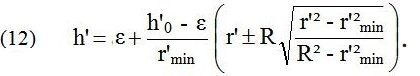
The equations combine to a contour equation
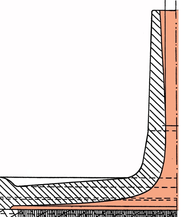
The narrowing of the entrance tube part of the header that is needed is small. It also serves the purpose of slightly accelerating the blood flow in the narrowed portion, which gives kinetic energy for the turn of the flow from axial to radial. A typical example is (without actual measures but drawn to scale) shown in the following figure.
Suitable shapes and dimensions for ultrasonic welding are shown here:
Headers with a rotating flow in the blood space
Attempts have been made to establish a rotating or “spiraling” flow of the blood over a bundle of fibers, which are arranged around a central plastic support that forms a core inside the bundle. That way the cut fiber ends form an annular area. The blood then enters tangentially into a circular distribution space over that area. This is, in the case of such a bundle design, actually a neat idea for having a more proper blood-flow situation in the header, but there are pitfalls...
The designs I have seen so far all suffer from one or both of these two problems:
The reason is that the flow velocity decreases along the circular distribution channel as flow is drained off into the fiber ends. Hence a residual flow at a considerably lower velocity, after going around in a full circle, wants to mix with the entering feed flow, which doesn’t work.
The solution is, therefore, quite simple, as I have shown in laboratory investigations: to maintain the flow velocity as constant as possible along the circular flow channel. This requires a linearly decreasing height of that flow channel so that it is only maybe a mm high or even less where it after a full circle meets the tangential feed tube. Thus the residual flow after a full circle meets the entering flow at approximately the same flow velocity, so that it easily mixes in with the entering flow without flow pattern disturbances. This way a neat circulating flow can be maintained all around the circle.
As is quite obvious, a neatly rotating flow cannot be established at the “venous” end of the dialyzer. It would, therefore, be quite logical to have another header shape here that is similar to a conventional header shape but with a more or less conical part in the center, inside the annularly shaped fiber-end area. One may also attempt to bundle the fiber ends together without a central dead space at this end, which is not easy.
External shape
The external shape of the blood tube parts of the headers – with an arrangement for connecting the tube from the blood pump and the return tube at the venous end – is defined in standards, which though some are national in fact are international, since they are basically all the same.
Beyond that the external shape also depends upon the way the header is fixed to the dialyzer sleeve: by screwing, ultrasonic welding or maybe in another way. Ultrasonic welding requires a suitable contact surface for the sonotrode and suitable shapes of the fusion regions in headers and dialyzer sleeve. The sealing of the blood space of the header to the cut polyurethane surface can be arranged with a rubber ring. In the case of ultrasonic welding a v-shaped circular wedge could be made to press into the polyurethane at the end of the welding process (see here).
Return to dialyzer optimization